Total Pageviews

Wednesday 30 July 2014

Launch Bay Elevated Walkway: Gantry supports (detailing)

Just a quick update as I complete the final card work and detailing on these pieces. I have come to realize that the central launch rail structure is not quite central, so I will have to redo the walkway on the far side from most of these shots (the side with the Thunderbolt model). Once these are done I will need a break from this project for a few days as the time involved is getting to me. Time to go out and marvel at that unfamiliar ball of fire in the sky.


Monday 28 July 2014

Launch Bay Elevated Walkway: Piston mechanism mock-up

Just a quick update on the initial designs for the pistons that give the walkway the illusion of being able to adjust it's height. The plastic tubes used for the pistons will not be sufficient to hold the structural integrity that the structure will need so I will be adding more foamcore to the mechanism to look like metal guides for the raising and lowering actions. These should further reinforce the structure and keep it in shape....literally.


Sunday 27 July 2014

Launch Bay Elevated Walkway: Concept sketch and initial work

So I have more or less settled on a design for the gantry supports. I will need to seriously bulk out the shape once the main structure is assembled so as to break up the boxy shape it currently has. This is one of the limitations of working with foamcore. You are generally stuck with flat sided shapes (and I am saying generally as I am not certain that you can not curve foamcore...I have been too busy to look it up).

So the photos show the side shapes for the upper and lower portion of this gantry. The gap is intended to give the idea that the gantry can move higher or lower depending on the ship in the cradle. That section will be filled with plastic tubing to represent the hydraulic pistons that make this movement possible. To be clear this piece will not actually be able to alter its height. It is hopefully just going to look like it can.

I have assembled the top support for the gantry and show them assembled and also show a shot of the walkway on top of its supports. The supports are clearly different widths to accommodate the walkway but their attachment points to the walkway will depend on their distance apart once they are on the edge of the elevator. I want these walkways to at least touch the central structure that I have been working on in parallel with this.

And yes I am aware the perspective in the sketch is shot. It is a mess of concepts smashed together and was used to design the card templates that I traced the pieces with. I will scan and post those later in case anyone is interested.


Friday 25 July 2014

And level 3 walkways are now done but...

...they are probably going to be used for an arch-gantry thingy that will extend over the tops of the elevators instead. The far end of the launch rails building will now be bulked out in a different way instead (still to be determined. this is why this takes so long). So I am sketching out ideas for the supports for this gantry and the rough idea is to have what looks like exposed pistons in the center of the column to imply that the gantry can be raised or lowered. If I get over my embarrassment at some of the designs I may scan the page of the other ideas I had.

Anyway, the walkways are done...but now they will need handrails and stuff. Sigh....

Thursday 24 July 2014

Landing Bay: Launch Rail Structure, Lower Levels

So now the process of working out how this structure is going to be bulked out has begun and this is where the process goes a bit more slowly. I find myself constantly going back and forth to the structure to test ideas out and design new elements. Advancement can be slow at times but it does improve the look of the piece considerably.

One main concern of this structure is the weight distribution. Currently it is delicately balanced around the middle but since the highest portion extends out from the center of gravity, the original assembly would easily tip forward. So I have to add more weight to the opposite end to fix this. Note that when this board is complete there will be the elevator structure supporting this part but since all of the structures will be removable to an extent, I would like this structure to stand on its own (also giving more versatility to the building). If necessary I will build and extra "foot" to support the building if used in other settings but I will see where this design process takes me.

Level 2 Walkways

Because of the size of the structure I decided I need to improve line of sight through the levels so that players will be less likely to lose track of models. I decided to do a grating effect using plastic needle point grids. Not my first choice but I had these grids laying around and I am trying to consume the mad assortment of materials that I have gathered as terrain bits, so in they go. These are made of a more vinyl-like plastic so I used white glue and superglue to bind the grid to the card, as well as adding some small cross supports to help support the grid. This was a really time-consuming step to design the first walkway but it served as a template for the opposite side. 

When it was done I still thought that the LOS was still not clear enough so I resolved to make the grating on the next level up even larger.

I also need to better secure the walkway so I added a block and pipe assembly to add support to the walkway. Note that because of all of the white glue used to hold the card that the foam core has warped slightly. Adding a short wall along the edge will help straighten it but this also means that when they are finally glued in place, I will have to ensure that they are pressed onto their supporting surfaces until the glue dries.


Third Level Walkways

This part is here just to show you the process of how I assemble these walkways. I had a rough idea for the main shape of the walkway but needed to design the exposed grating. I left about 1.5 cm between each shape cut out of the walkway. The card pieces over the top will overlap into these shape by about 0.5 cm to hide the edges of the grating pieces and to further secure the grating pieces into the structure.

The card overlay, once designed, was used as a template to help design all of these parts so that by the end I had all of my parts sketched and cut. Now I have to line the inside edges of the cut shape with card to protect the foam and further strengthen the piece.


This has the added benefit of adding a lot of weight to these walkways so that they will ad bulk to this end of the structure as I wanted. These are still a WIP but I have been snapping shots as I go.

More as it happens. 


Monday 21 July 2014

Landing Bay: Launch Rails Structure


I have roughed out the sides for the central structure. It looks very one dimensional right now but it will be broadened considerably. Each level up is 3 inches above the previous level. That measurement is from floor surface to floor surface. I marked out all possible levels (6) in a new sheet of foam core placed in a landscape orientation. Then I marked down roughly equal steps until the third level.  Each rise up will include 2 steps mounted at 1 inch intervals which should give any model up to a dreadnought the mobility it needs to traverse the structure.

Once the interior floors are laid out I will begin planning the various balconies that will expand this structure laterally.

For anyone wondering about the design, in essence I wanted a structure that would rise at an angle. I stepped the slope to make it look more “Imperial” or at least my interpretation of it.
All of the various ports in the walls are there to make it as easy as possible to maneuver models within the structure itself. So the structure was essentially designed as I went on to the very sheet of foam core I cut it out of. I had tried several times to try to design the structure but aside from the sloping design I just could not get a good sense of how the structure would actually look on the table. Drawing it as I went allowed me to immediately assess any design elements in ‘situ’, so that I had a much better sense of how my drawings impacted the design. Am I 100% happy? No not really. It did not turn out as I had envisioned but I have some ideas for what I do have that will allow me to punch up the shape of the structure. This is an important build as this structure is one of the design elements that are going to have to add depth to the playing surface.

After this one is done, there is one more structure I would like to put roughly around the teleport pad. It may even connect to this central structure but that too will be designed as I go.

The photos below show the side wall design I somehow made organically (can I use the term “organically” without sounding pretentious?). The main guide in the design is the requirement that I have levels that are each 3 inches high and that the structure rises in a slope like fashion. What you see is the result of my attempts to refine those initial elements, for better or worse. Now I just have to make them even better. 

And in case anyone is wondering, why do I build as I go? because the board has to be playable. And sometimes what looks great in your minds eye will not translate into an effective playing surface so why devote time and effort to just that? You have to keep in mind that regardless of what you are building, you are creating a playing surface for the game. Imagining the shape of a structure is not the same as seeing how it affects movement and LOS. My 2% of a dollar. Anyway photos and stuff. 

One shows how the floors in the structure were glued in (i.e. one side at a time). On reflection i could have done them individually but there were some rather fragile elements to the building shape that I was trying to preserve (note: I was not successful) but it will work in the long run. The rest just show a mock up of the structure in position. I nly included one set of arches for the photo as it was again just to get a sense of scale on the table.


Thursday 10 July 2014

Landing Bay Terrain

So I have spent a week working away on this project and am now taking a break to work on a set of 40K Knights. It will be an interesting challenge that will involve making use of a suggested way to sculpt icons that I had seen years ago. I guess I will be testing how good my memory is too.

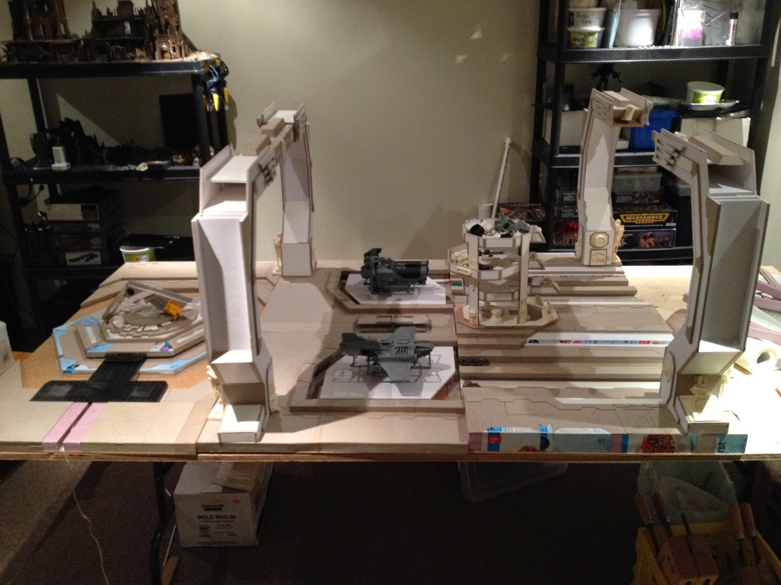
The photos are grouped in three different sections separately, the last showing a  mock up of all parts assembled in the current form of the table.
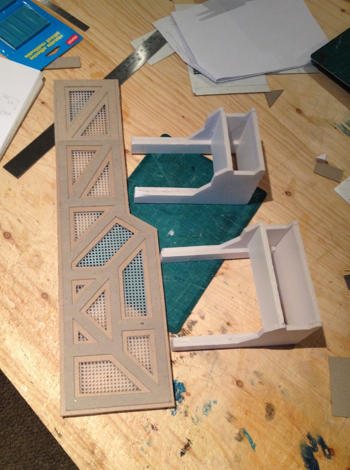
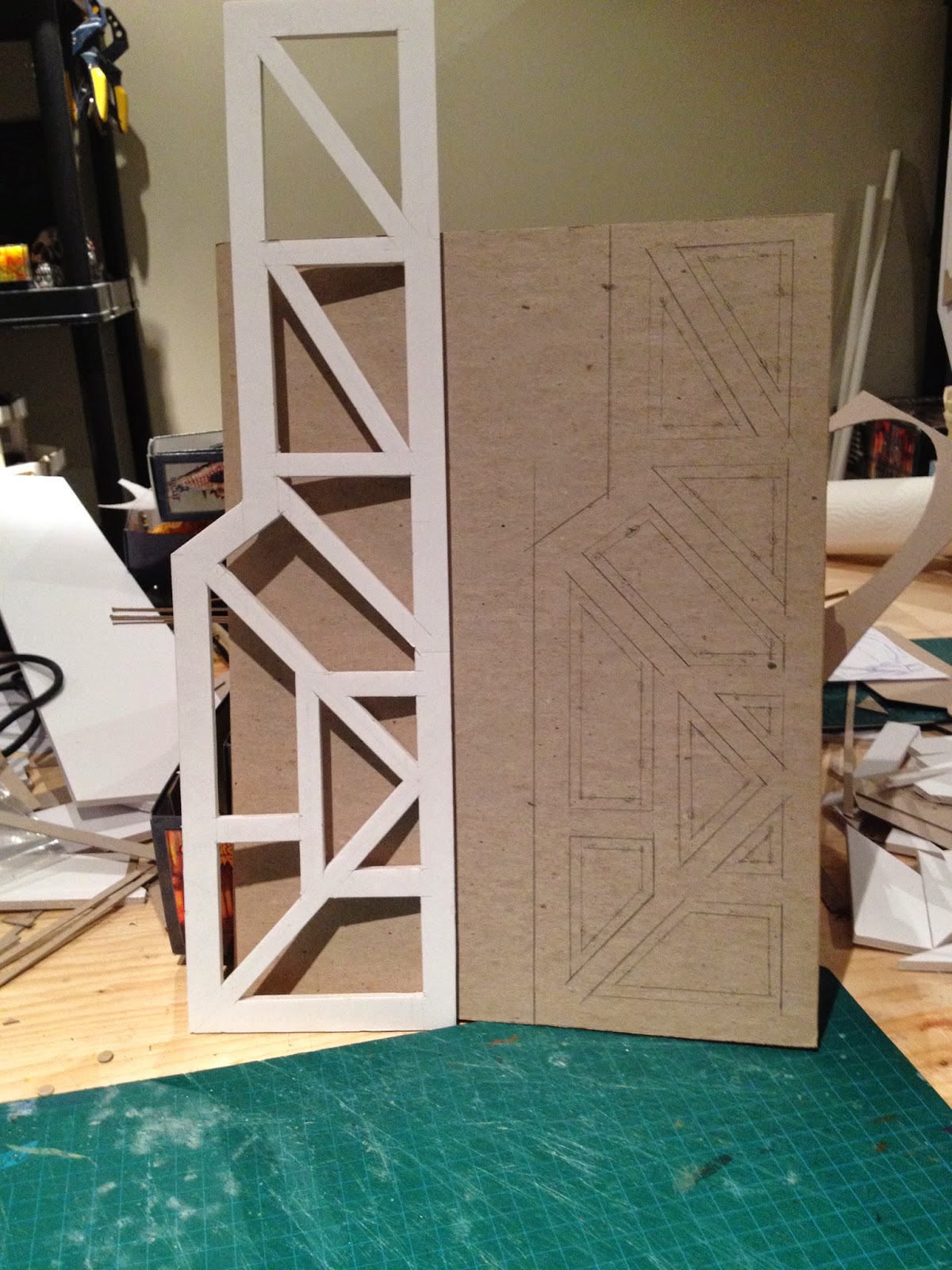
The Teleport Pad

Rather than awkwardly squeezing this piece into a corner I have made it the central feature of it's section. I am planning on putting two high partial structures on either side of the teleport pad to add some height but I have an idea for another structure that can potentially give a sense of surrounding the pad without significantly impeding movement (specifically vehicle movement) too much.

The lighting channels underneath the pad are now finalized and have been lined with card. I have also added an overhang of card to the portions which will hold the wires in so that it is easier to insert the lights and place the lid on.


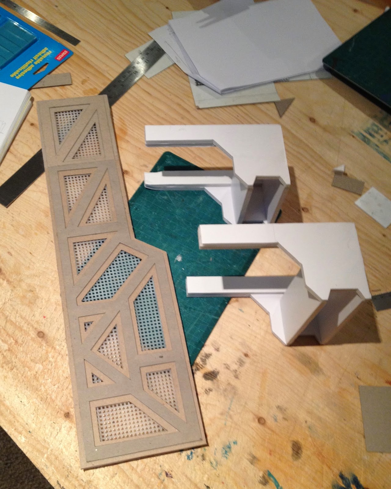
The lid portion may have channels cut into three of the lower steps. This would allow more light from the light system to shine through the base rather than just giving a ground effect off of the lowest level.
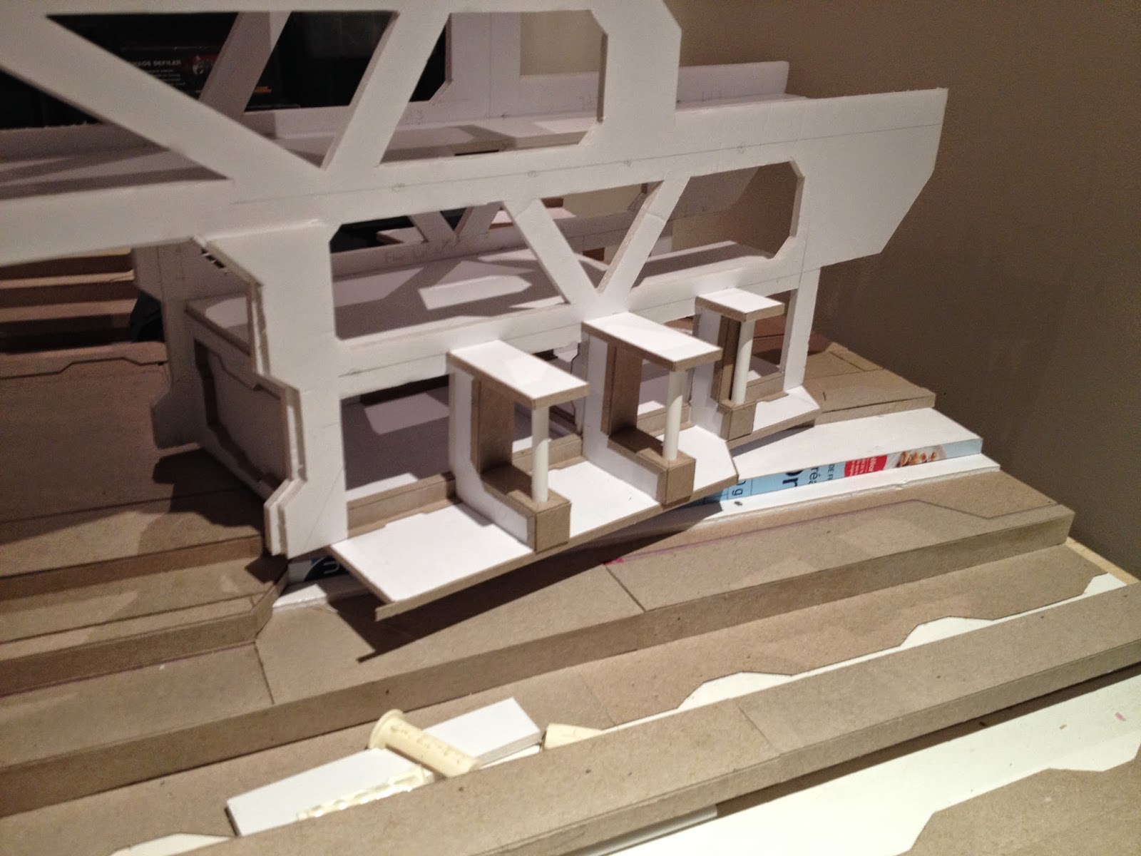
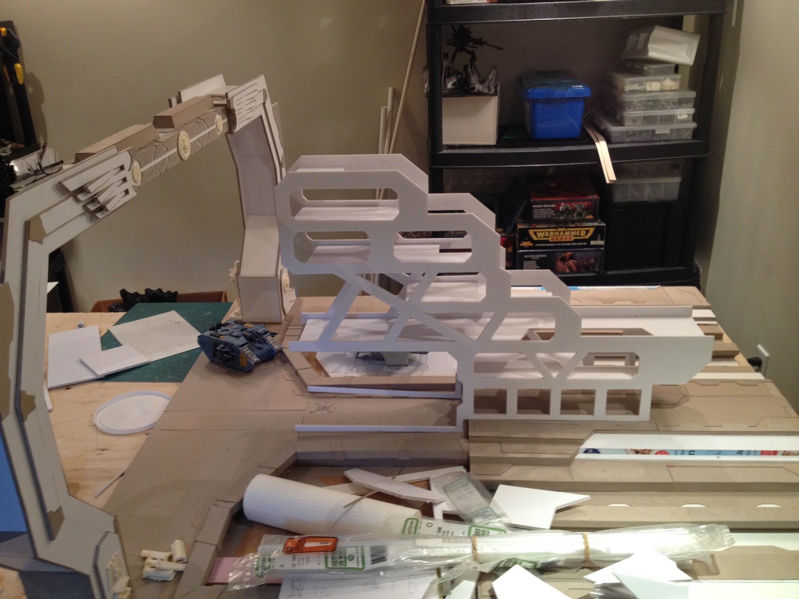


The Plane Elevators

There is to be a largish central structure here that will probably extend over an ammo elevator that will be between the two planes.

I have cut out lengths of foamcore to make the appearance of open doors but I have to decide if I want them above or below the lighting system. It is only a thin strip of the door showing.

I have to work out the details of the elevators, specifically the mechanisms underneath and the carriages carrying the planes. I am also considering having different elevators to have the planes at different heights but that seems needlessly complex.
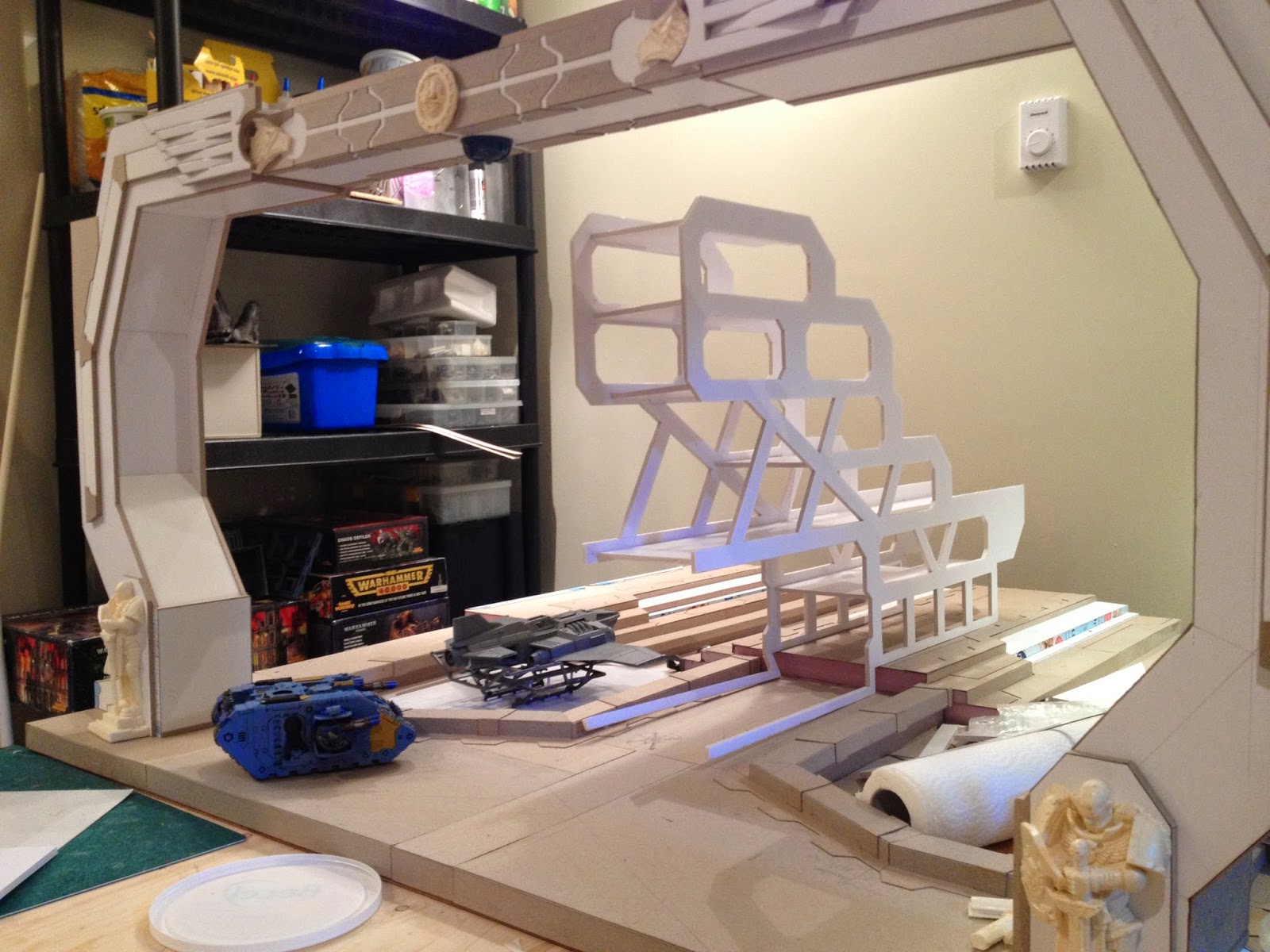


New Layout

By spacing the arches more it is much more player friendly but the whole thing looks too flat. Nevertheless all of this is mostly just the base of the board sections. It will be the details that add depth to the board.


Update:

By the way, I would not recommend using the card from cereal boxes, at least not the ones I used. I had decided on it as a material as it was readily available and a by product of breakfast.

However the card stock is too thin and too easily warps from even the small amounts of moisture in the glue. This is part of the reason a lot of heavier card stock was added to the teleport pad (i.e. to smooth out its appearance as well as adding some much needed detail).